


When an LED work light fails early, the LEDs themselves are rarely the first thing to go. What fails is the lamp around them: heat that is not carried away, a solder joint that cracks, a lamp that is wired backwards, a lens that turns yellow. Each of these usually traces back to a place where the lamp was made cheaper.
This guide goes through seven of those places, what each one leads to in service, and how we build our lamps to lower the chance of it. It is written for engineers and buyers comparing suppliers, because almost none of these choices can be seen on a spec sheet or in a photo.
Why heat decides how long an LED work light lasts
An LED turns part of its power into light and most of the rest into heat at the junction, the point inside the chip where light is produced. The US Department of Energy puts it plainly: heat at the junction is the primary cause of lumen depreciation, and while a short spell at high temperature can be reversed, continuous high-temperature operation causes a permanent loss of light output.
That heat has to travel from the LED through the circuit board, through a layer of thermal interface material and into the housing, which passes it to the air. Three of the seven cost savings below sit on that path. Each one adds resistance to the heat flow, so the LED runs hotter than it was designed to, dims faster and, at the worst positions in the lamp, burns out.
1. The housing: magnesium alloy, and walls that are too thin
A lamp's housing is also its heat sink. Die-cast aluminium A380 conducts heat at 96 W/m·K. The two magnesium alloys most used for die casting conduct much less: AZ91D at 51 W/m·K and AM60B at 61, according to published alloy data. Magnesium is about a third lighter and casts in thin walls, which lowers material cost, but a housing in these alloys moves heat away from the LEDs more slowly than the same shape in aluminium. Alloy choice matters here: some magnesium alloys, such as AM20 at 94 W/m·K, come close to aluminium, which is why the grade is worth asking for by name.
| Alloy | Type | Thermal conductivity (W/m·K) | Density (g/cm³) |
|---|---|---|---|
| A380 | Die-cast aluminium | 96 | 2.74 |
| AM60B | Die-cast magnesium | 61 | 1.80 |
| AZ91D | Die-cast magnesium | 51 | 1.81 |
Wall thickness works the same way. A thinner base and thinner fins hold less metal to spread the heat, so the area under each LED runs hotter.
How we build it: our housings are die-cast aluminium alloy with the heat sink cast in, and the housing is sized to the power of each model rather than shared across wattages.
2. The circuit board: too thin, with a weak insulating layer
LED work lights mount their LEDs on metal-core boards: a thin copper circuit, an insulating layer and an aluminium base. The insulating layer is the bottleneck. Cree's board design guidance notes that thermal performance falls off sharply when that layer conducts less than about 2 W/m·K, and it shows that the same material can be quoted at 2.2 W/m·K by the standard test method or above 30 by a non-standard one. A figure on a board datasheet is only comparable if you know how it was measured.
A thinner aluminium base spreads heat less before it reaches the housing, which concentrates heat under the LEDs.
How we build it: the board and its thickness are chosen for the power of each model, not for the lowest board price.
3. The thermal paste: uneven, or the wrong grade
Between the board and the housing there is always a gap, however flat both surfaces look. Air in that gap conducts about 0.024 W/m·K, so a thermal interface material, usually a paste or pad, fills it at roughly 0.1 to 10 W/m·K. Cree's thermal management guide sums up the rule as "thin to win": the layer has to be thin, even and complete. Too thick and it adds resistance; missed spots leave air; some materials pump out of the joint over repeated heating and cooling and leave voids behind.
Paste applied by hand, or a cheaper compound with low conductivity, gives exactly those faults. The lamp passes a quick test at the factory and runs hot in the field.
How we build it: the paste is applied as an even layer across the whole board, with a compound chosen for its thermal conductivity rather than its price.
4. The soldering: poor reflow control
LEDs and driver components are soldered in a reflow oven that follows a set temperature profile. If the peak temperature is too low or the solder stays molten too briefly, the result is a cold joint that looks sound and conducts, but is weak. On a vehicle, that joint then sees two kinds of stress: temperature cycling, which fatigues solder a little with every warm-up and cool-down, and vibration, which flexes the board until a weakened joint cracks. The lamp starts to flicker, then goes out, often only when the machine is running.
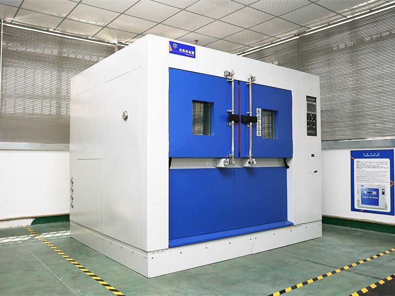
How we build it: our SMT line runs a controlled reflow profile, and each design is run on our own vibration table to the customer's profile and through thermal shock cycling before production. Before shipment, every lamp is powered on for a burn-in test on alternating 12 V and 24 V input. For how vibration ratings are written, see vibration rating.
5. Reverse polarity: no protection when the leads are swapped
Work lights are often wired in the field, on machines where both leads are black or the colour code has faded. A lamp with no reverse-polarity protection can be damaged the first time positive and negative are swapped. The vehicle side is not gentle either: ISO 16750-2, the standard for electrical loads on road vehicles, includes test items for reversed voltage and for load dump, the voltage surge when a battery disconnects while the alternator is charging.
How we build it: our drivers include reverse-polarity protection, and our work lamps run on 9–32 V DC so one part covers 12 V and 24 V machines.
6. The lens: plastic that turns yellow
Polycarbonate is tough, which is why it is used for work light lenses, but unstabilised polycarbonate yellows under ultraviolet light, transmits less light and becomes more brittle. Resin makers sell UV-stabilised grades and coatings for exactly this reason. A cheaper lens looks the same on the day of delivery and, after time outdoors, lets noticeably less light through. More on lens materials in polycarbonate lens.
How we build it: most of our lenses are anti-UV polycarbonate, some models have a surface-hardened lens, and some use glass instead.
7. The seals: silicone that outgasses and fogs the lens
A work light is sealed to keep water out, which also keeps in whatever the materials inside give off. Glues, gaskets, O-rings and potting compounds can release volatile compounds when they get hot. In a closed lamp these condense on the inside of the lens as a haze that looks like dirt, and they can also be absorbed by the LEDs' own silicone and discolour it. Cree's chemical compatibility note shows a nearly sealed luminaire whose light had visibly yellowed after less than 100 hours, and a sealed test group that lost 90% of its light output after 450 hours, while a group whose enclosure was vented recovered almost all of its lost output within 24 hours.
Sealing is still necessary. The point is to use sealing materials that do not outgas at the lamp's operating temperature, and to test the finished lamp hot.
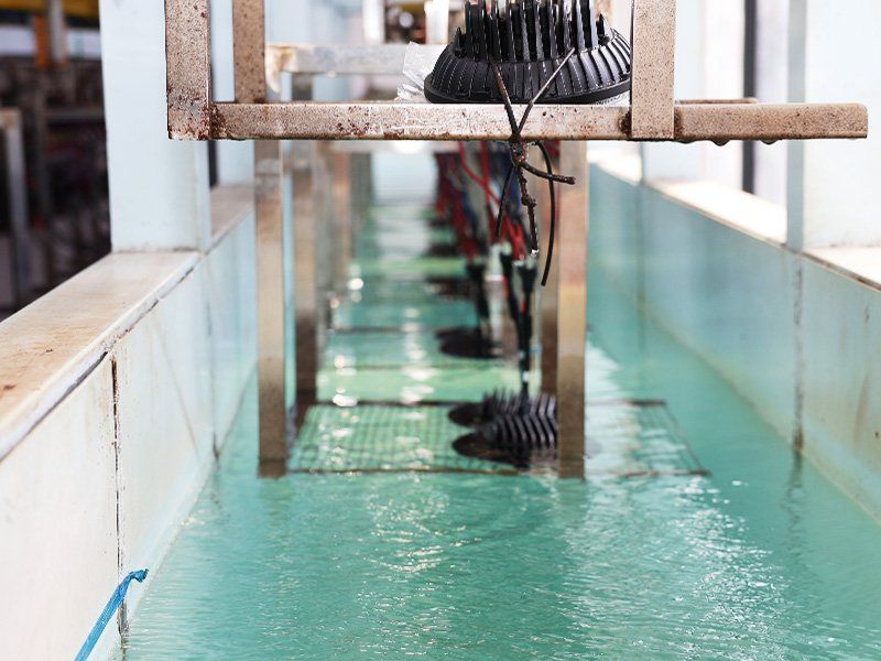
How we build it: sealing materials are chosen with outgassing in mind, the driver is potted, and the sealed lamp goes through our water immersion, high-pressure spray and thermal shock tests. How IP ratings for sealing compare is covered in IP69K vs IP68.
Seven savings, what they cause and what to ask
| Where the saving is made | What it leads to | What to ask the supplier |
|---|---|---|
| Magnesium housing alloy, thin walls | LEDs run hot, faster dimming, some LEDs burn out | Housing alloy grade and wall thickness |
| Thin board, weak insulating layer | Heat trapped under the LEDs | Board type, and how the insulating layer's conductivity was measured |
| Uneven or low-grade thermal paste | Hot spots, faster dimming | Thermal interface material and how it is applied |
| Poor reflow control | Flicker, then failure under vibration | Reflow profile control, vibration and thermal shock testing |
| No reverse-polarity protection | Lamp destroyed when wired backwards | Is reverse-polarity protection built in |
| Unstabilised lens | Yellowing, less light | Lens material and UV stabilisation |
| Outgassing seal materials | Haze inside the lens, LED discolouration | Sealing materials and hot testing of the sealed lamp |
Questions to put to any supplier
The table covers the seven savings. Three more questions are worth asking whoever makes your lamps, because they depend on the model and the programme:
Does the lamp have a breather vent or membrane, and how is condensation handled?
Does the driver reduce power if the lamp overheats?
Which transient tests, such as load dump, has the lamp passed, and to which standard?
Comparable specs between suppliers are covered in LED lights for heavy equipment. For the range, see LED work lights.
If a lamp you use today keeps failing in one of these ways, send us the model, the machine and a description of the failure. We will tell you which of the seven is the likely cause and what we would change.
Frequently asked questions
What causes LED work lights to burn out quickly?
Usually heat. If the housing, board or thermal paste cannot carry heat away from the LEDs, they run hotter than designed, dim faster and in the worst positions burn out. Poor soldering and missing reverse-polarity protection cause the sudden failures.
Why does my LED work light flicker when the machine is running?
Flicker that appears with engine vibration often points to a cracked solder joint or a loose connection inside the lamp. Temperature cycling weakens solder over time, and vibration opens the crack.
Why is there haze inside my LED work light?
Either moisture has got past a seal, or materials inside the lamp have outgassed and condensed on the lens. Heat drives outgassing, so it shows up most in lamps that run hot.
Can wiring an LED work light backwards damage it?
It can if the lamp has no reverse-polarity protection. Ask the supplier whether the driver is protected before lamps are fitted by crews in the field.